
(click on diagram to enlarge it)The F6IRF antenna monoband phasing device: It just requires 3x2RT switches. Phase delays are obtained using 3 lenghts of coax cables 1/8wl (45degrees) 1/4(90degrees) and 1/2 (180degrees). Combining the 3 allows 0 to 315 degrees variation by 45 degrees steps. The device is inserted in one of the antenna line, after the stackmatch. I have used 5D-FB foam coax cable, and high-current switches (losses and impedance mismatch are neglectable and it was tested at 1KW without problem...)
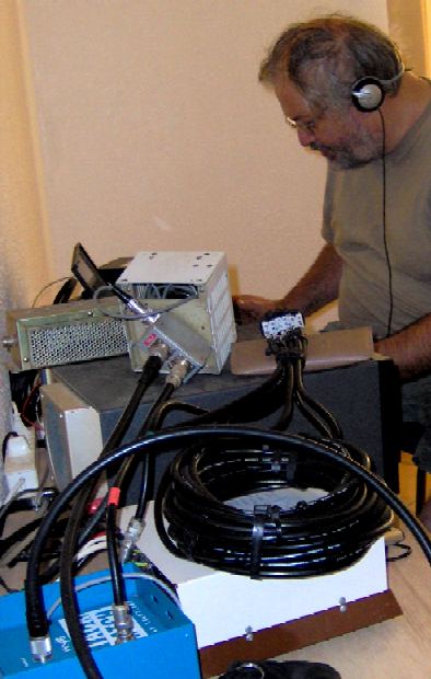
The phasing device in service, during the 2006 CQWWDX-contest from CN2WW (SOSB20m).
From Morroco, it is a big advantage to keep one antenna toward EU, while playing with the second one, to get mults in exotic directions, or to boost the EU rate, with the second one toward states...
Potential applications and benefits
First example: The 2 antennas at 12m are in the same plane pointing at the same desired direction and spaced horizontaly by 0.8wl (my home setup to JA). As shown by the following examples, varying the phase allow some direction adjustment, which is quite useful as the horizontal pattern is quite narrow (even with the simple 2elements used for the simulation - just imagine with 2x 5 elements).

 Click on images to enlarge them. Here, the 2 antennas are at 12m agl, in the same plane, perpendicular to the desired direction, spaced by 0.8wl and fed in phase (I.E. identical antennas with equal lengths of coax cable). In red is the pattern of 1 antenna, in black the pattern of the stack. The gain of the stack is 3dB compaired to a single antenna, but the pattern becomes quite narrow.
Left: the antennas are fed with 90degrees relationship (in red the pattern of a single antenna as reference). Right: The antennas are fed with 180 degrees relationship, the pattern becomes bidirectionnal, with a nul in the main direction (in blue the pattern of the antennas in phase, in red a single antenna). By varying the phase, it is therefore pssoible to adjust the pattern to any value between +/-30degrees compaired to the perpendicular axis of the antennas.
Second example: the 2 antennas are not in the same plane, and one antenna is turned by 45 degrees...

right: The pattern of each antenna fed separatly. To be noted, the backlobe of each antenna is distorted by the presence of the other one.

Left: one antenna phased out by 45degrees, the result (in black) is almost a virtual antenna pointing between the 2. Center: the phase relation is 225degrees, the bidirectionnal pattern is almost restored. Right: the phase relation is now 315 degrees, the bidirectionnal feature remains but with a substantial advantage for one of the antenna.
Third example: Here the 2 antennas are pointing at 90 degrees directions; you may think that the phase relation is less important in this case... it is, but still, it is not completly useless to play on the phase...

center: the 2 antennas are fed in phase, the expected bidirectionnal pattern is here, but with some distorsion (in red the pattern of a single antenna)The 3dB loss is normal taking into account that each antenna is fed with half of the power. Right: In black the 2 antennas are fed with 180 degrees phase relationship (in red, the antennas in phase, in blue a single antenna as reference).
Fourth example: Like in example 2, the 2 antennas are looking at 45 degrees directions, but it is the second antenna that has been turned (as shown in picture below).
Left: the patern of each antenna fed separatly. Right: the patterns obtained when phasing the 2 antennas with 0, 90, 180 and 270 degrees phase relationship.
 Comments : This system was built-up for 20m band, however, it is also usable on 15 and 10 (with 90 degrees step on 10 and something in between on 15). It is also usable on 40 but then the phase limit is 315/2=157.5 degrees. Of course it is possible to add lines and switches if you are interested by multiband capability, but the spacing of the antennas will have to be somehow "compromised", especialy if you are looking for "extra gain"(as shown in example 1). All simulations have been done using MMANA203 by JE3HHT and can be verified using NEC2 engine for MMANA by UA3AVR (allows MMANA antenna files to be converted to NEC2 files).
 Does it work ?: The answer is yes ! just moving one switch maybe sufficient to get a station out of the noise and QRM, and this has been verified in several contests....
(*) To be accurate Array-solutions commercializes a "180degrees-unphaser" which allows high angle radiation for verticaly stacked yagis.
.jpg)
Above my home setup used in 2005 in more than 30 contests (a 2elts steppIR and an OB6-3M). Here the setup used at CN2WW for the CQWW-CW 2006 (SOSB20 - 3 elts SteppIR and 3elts spiderbeam) .
The maa and nec files are available here
http://mangafight.free.fr/2x2elts%20maa%20and%20nec.zip
Une version Française est disponible ici en pdf
http://mangafight.free.fr/Phaser.pdf
No comments:
Post a Comment